How to export Gerber files from Eagle file?
What is Eagle software?
EAGLE is a scriptable electronic design automation (EDA) application with schematic capture, printed circuit board (PCB) layout, auto-router, and computer-aided manufacturing (CAM) features. EAGLE stands for Easily Applicable Graphical Layout Editor (German: Einfach Anzuwendender Grafischer Layout-Editor) and is developed by CadSoft Computer GmbH. The company was acquired by Autodesk Inc. in 2016. EAGLE contains a schematic editor, for designing circuit diagrams. Schematics are stored in files.SCH extension, parts are defined in device libraries with.LBR extension. Parts can be placed on many sheets and connected together through ports.
The PCB layout editor stores board files with the extension.BRD. It allows back-annotation to the schematic and auto-routing to automatically connect traces based on the connections defined in the schematic.
When you finished your PCB design in Eagle, you could generate Gerber files that are needed by the PCB manufacturer. This NextPCB article is telling you how to export the Gerber file from Eagle software.
Step 1.Open the CAM Processor
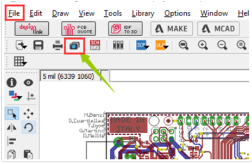
Open your PCB layout (.brd) file in Eagle, Click the “ CAM” button or choose “File -> CAM Processor”.This will open the CAM Processor tool that is used to generate the files.

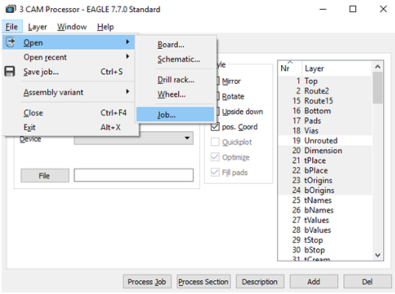
Step 2.Click File -> Open -> Job

Step 3.Then navigate to your default EAGLE cam folder, choose the GERBER_RS274x.cam file, press Open.

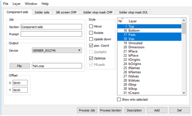
Step 4.Adding a second silkscreen (Optional)
If you look at the Layer options, it doesn’t have a file for silk screen bottom. But if you need a silkscreen on the bottom layer as well, follow these steps:
a. Click “Add”
b. Change Section to something like “Silk Screen SOL”
c. Change File to “%N.pls”
d. Deselect all layers
e. Select layers 20 “Dimension”, 22 “blames” and 26 “blames”
Step 5.Select the Process Job button to create all of your Gerber files. You can find all of your generated Gerber files in the Autodesk EAGLEControl Panel in your project folder.
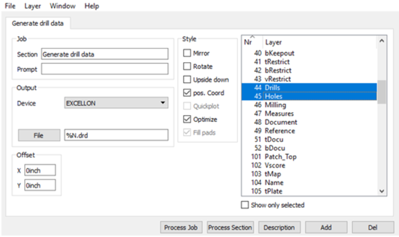
Step 6.Generating Your Drill File
a. Select the CAM Processor at the top of your interface or
select File » CAM Processor to open the CAM processor dialog.
b. You now need to load a drill CAM job to get things started. Select File » Open » Job,
and in your default EAGLE cam folder select the excellent. cam file, then select Open.
c. you'll now have a single Generate drill data tab available, which will grab the data from layers 44 Drills and
45 Holes, just what you need. Select the Process Job button to generate this file.

After those steps, Gerber files and Drill data have been exported from Eagle software.
Feel free to contact us: support@nextpcb.com
if you have any more questions.
Related Articles
How to Export Gerber files From Diptrace Software?
DipTrace is an EDA/CAD software for creating schematic diagrams and printed circuit boards. The developers provide a multi-lingual interface and tutorials (currently available in English and 21 other languages). DipTrace has 4 modules: schematic ...How to export Gerber file from KiCad?
Gerber files are the industry standard for PCB manufacturing, containing all the necessary data for fabrication. If you're using KiCad and planning to order your PCB from NextPCB, this guide will walk you through the correct steps to generate and ...When will the engineers check the Gerber files?
After completing checkout and payment, our engineers will begin file review for any order or engineering issues. If any problems are found, we will send you an email to notify you of the issues. Once the issues have been resolved, the order will be ...How to place a PCB order?
Navigate to the NextPCB order page from the top menu and upload your PCB Gerber files on the order page. The website will parse the file and may extract parameters from the files and fill in these details for you such as PCB Size, Layer Count, Min. ...Clarification on Price Differences
Q1: Why might there be a price difference after payment? A1: Price differences may occur for several reasons, including: 1.Increased Processing Fees During File Review The initial price is calculated by our system, but some processes may not be fully ...